Dav’s PiTank
This weekend, my Raspberry Pi Robot tank took its first steps, or trundles, under its own power. The hardware’s been assembled so that it’s completely mobile, a USB battery pack is keeping the controls running and the user interface has been fixed a bit so it’s easier to steer.
The hardware set-up so far is:
- Dagu 5 Rover Chassis
- Dagu’s motor controller PCB
- Dav’s simple 3.3v to 5v glue circuitry
- The Raspberry Pi!
- USB Wireless Ethernet adapter
- Logitech USB Webcam
- Anker 5600mAh Battery
- Some screws and metal spacers that came with the motor controller PCB and a curry takeaway lid
Whereas the software stack running on the Pi and my mobile phone’s web browser is:
- Simple HTML and Javascript UI to provide direction controls and display the latest image from the webcam
- Lighttpd and some trivial FastCGI python to receive commands from the UI and relay them to a unix pipe
- Another simple python script that uses RPi.GPIO to output commands to the Pi’s GPIO pins
- fswebcam to capture frames from the webcam and save them to a file for the web server
What’s changed since last time?
Mobile power

The most significant new addition is the Anker 5600mAh Battery, which is good value for money compared to other brands. It’s essentially a battery with a builtin charging circuit, charge level display and white LED in case you need a torch. With the batteries, bigger is normally better, but I estimated that this one will do the job very well and still cost less than twenty pounds.
The Pi consumes about 700mA or so, depending upon what it’s up to. According to its datasheet, my Linksys USB600 Wifi adapter consumes a maximum of 480mA when transmitting. I haven’t found a figure quoted for the webcam, and I’m too lazy to measure it, so I’ll just assume it’s a worst case of half an amp when it’s capturing an image and that it’s running for about half the time, so call it 250mA. I haven’t yet measured how much power the control circuity uses.
Those numbers added up gives us a total run time of just less than 4 hours of trucking about the place, which is more than enough for this stage of the project.
For a comparision, the motors in the chassis consume a maximum of 2.5A and I’ve used 2700mAh rechargable AAs, so that’s a bit over half an hour of maximum drive on a charge, although it will likely be more than that as my floor shouldn’t need maximum drive power. I haven’t yet added some analogue inputs so the Pi can monitor actual motor power consumption.
Control responsiveness
Traditional analogue radio controls operating servos operate near enough instantly, whereas my proof of concept, simple to configure CGI python script took between 500 and 1500ms to change a GPIO pin after the input button was pressed. This is fine for putting a tick in the ‘can control it’ box, but half a second lag makes it surprisingly fun to control with any degree of accuracy. So that had to go.
First up against the wall was running the python GPIO driver directly in the CGI script, that extension takes precious time to initialise itself, test it can access /dev/mem, ensure the pins are set for output etc, so I split that out into a seperate control script that ran all the time in a background process and waited for input.
That got us down to about 500ms response time, which is still pants. For those readers who don’t run web servers for a living, ‘CGI’ is a very basic way of connecting a program up to a web server and it’s rare to see it used today. The reason it takes 500ms to run is that CGI starts up a new program for every new web request, which for an interpreted language like python means it then has to initialise any modules the script includes, parse the script and then execute it. The Pi’s ARM core does run at 700Mhz, but it’s still doing work that it doesn’t need to.
The solution is to run an instance of Python all of the time, so it can cache the python language itself as well as my script, so all it has to do is listen for a request, look at the parameters and write a character to a file. For this, I’m using FastCGI, which is itself somewhat old fashioned but it’s quicker to configure in Lighttpd than WSGI:
 sudo apt-get install python-flup

 fastcgi.server = (
   ".py" => (
     "python-fcgi" => (
       "socket" => "/tmp/fastcgi.python.socket",
       "bin-path" => "/var/www/cgi-bin/fcgiPipe.py",
       "check-local" => "disable",
       "max-procs" => 1)
   )
 )
We also have to change our Python code so that it expects to be run using FastCGI. For this, we need the flup library which is included in Raspbian and takes care of everything between the web server and our python. This library also encourages us to write our code in a more structured way as we have a single function as the entry point for all HTTP requests into our project. In my code, cgiPipe and fcgiPipe do pretty much the same thing, so it’s a good illustration of what code is required for FastCGI.
That gets us down to something approaching fast ‘enough’, although I suspect it will need further work once the Pi’s cpu gets busier with the control work I’ve got in mind
The code, as ever, is up on GitHub
Mechanical assembly
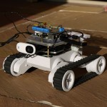
As you can see from the photograph, all I’ve really done so far is to add a plastic shelf about 5 cm above the ‘deck’ of the robot chassis, which leaves enough space in the chassis for the batteries, controller PCB and webcam and enough space on the shelf for the Pi and my breadboard with its fragile interface circuits. I say fragile, but it survived flipping onto its top when it tried to drive up a wall without any of the wires coming loose.
I found the plastic lid to be perfect for a shelf, it’s easy enough to drill holes through, it’s almost exactly the same size as the chassis and it’s plenty strong enough to support the entire chassis if it needs to.
Next steps
I do intend to catch up with writing up the robot’s design in a more logical order: starting with turning LEDs on and off, hooking that up to a web page, turning it up to 5v, sidestepping into USB web cams, before carrying on. I’m really enjoying this robotics game so far, it’s using such a fun variety of skills from electronics, through sysadmin to programming and AI.
My plan is to do a more robust job of connecting the modules together, I’ve got an order arriving this week from Proto-pic of some modular hookup wires and I’ve found somewhere cheap on eBay to buy a small pack of veroboard from. Why on earth is stripboard so very expensive!? Anyway, that will let me do away with the breadboard and connect to more of the pins on the controller PCB, so I can change direction on the motors.
I’d also like to try doing some cheap PWM using a python loop. General purpose multitasking operating systems and interpreted languages are a bad choice for this sort of thing, but I’ll be happy if I can get something like 0, 33%, 66% and 100% duty cycles from the output pins without flatlining the CPU.
There’s also this very interesting forum thread where somebody has written a kernel driver for the Pi that very cunningly uses DMA to drive PWM on the GPIO pins in hardware to a good accuracy level. As I also intend to use i2c and spi in the near future, I’ll have to swap over to using kernel drivers instead of RPi.GPIO and /dev/mem anyway.
Finally, once I’ve got some hookup wires, I intend to connect up a small character LCD I’ve got so that the Pi can talk to me without needing the television. For a start it will be displaying its current command and its IP address, but that’s only the beginning. I’ve found some very cheap SPI LCD modules on eBay that are on order that should be good for graphics, so it can start to map its surroundings.
I’m pretty much going to wait for Quick2Wire’s Analogue input board before I start to connect up sensors to the Pi, although I only need a couple of counter ICs and probably shift registers to start watching the quadrature inputs from the axles.
In no particular order, I want to start with it monitoring the motor current use so it cuts out before stalling. I also want it to cut out if it senses it’s about to crash or its stopped making progress. A couple of forward facing IF range finders are a good place to start there. I also had the idea of pulling apart a cheap USB optical mouse and mounting its LED and sensor on the base, that should also give it an idea of whether the chassis is actually moving or not.
Hi Dav,
I found your blog and was very interested, I am trying to do a similar thing, but with a custom chassis, motors, e.t.c, but I was having a lot of trouble with the code side, getting very close real time control to the GPIO over the web using python. You seem to have accomplished what I have had trouble doing, so I was wondering if you would mind explaining exactly how you got your code to work and how you have set it up.
Thanks
Jamie 🙂
Hi Jamie,
Thanks for getting in touch. I haven’t yet worked out how to present the full set up in a way that’s easy to digest, some people prefer more detail in certain areas than other people and if I’m not careful it would turn into a small book! I’ve got half a post already drafted which covers the code’s building blocks, albeit without the robot chassis attached, I’ll see about getting that finalised this week some time.
Cheers!
Dav
Hi,
First, your project is amazing !
Second, i have some questions 🙂
1. How do you improve the fact the the RasPi has only one PWM ? (and control 2 motor with one PWM)
2. The power supply is like USB battry -> RasPi -> Dav’s 3 to 5 -> Dagu PCB ?
Thanks
Arnaud.
Hi Arnaud,
Thanks for stopping by and taking the time to say hello.
For driving my robot chassis about the place, I don’t require particularly precise control of the motors as I’m using a human to issue simple commands like ‘forward’ and ‘stop’. That means I can completely cheat on the pulse width modulation and do it very approximately without using the hardware support from the RasPi’s GPIO pin 4.
At the moment, each motor can be driven at one of three speeds: Full (just switch the output logic to 1), Medium (30% mark / space ratio) and Slow (20% mark / space). I switch that in my Python control loop. It aims for about 10Hz, but in reality that’s going to jitter by at least 20% because it’s running in an interpreted language on a general purpose operating system that I’ve got doing other things at the same time. I don’t know if running it any faster would incur switching losses from the Dagu PCB’s transistors, or if Python would be able to keep up but this does the job for now.
I’ll need finer motor control, at least 10 steps if not more, if I hook up an analogue controller, like an Android phone’s tilt sensors or a WiiMote or Balance board or something. That’s when the RasPi probably has to bow out and issue commands to something with realtime support like Arduino.
As to your other question, I actually have two power supplies, mostly because it was quicker than shielding the RasPi’s power input from any noise from the motors. I’ve got a clip of 6 rechargeable AA batteries directly connected to the Dagu PCB’s motor power input, used to switch the motors. The USB Battery connects to the RasPi’s USB 5v input. The RasPi’s 5v output is used to power the Dagu PCB’s control logic and its 3v3 GPIO outputs are switched up to 5v to connect to the motor PWM and direction inputs on the Dagu PCB.
Cheers!
Dav